27+ traffic light block diagram
Block Diagram The traffic signal control system consists of three parts. 10 Block Diagram of a Closed loop Traffic Light Control The block diagram as shown in fig 10 is powered by a 5v regulated power supply.

Traffic Lights For Model Cars Or Model Railways Circuit Diagram Traffic Light Circuit Diagram Model Railway
Timer T T has a frequencyf1 and duty ratioD to control sequence.

. Universal block diagram of pulse radar. This project describes a one-way traffic light system using NXP Semiconductors 74HC4017N decade counter. Mainly by traffic lights and will reduce the amount of traffic jams especially during rush hour.
Basic traffic light schematic diagram. Traffic Light Diagram classic Use Createlys easy online diagram editor to edit this diagram collaborate with others and export results to multiple image formats. CIRCUIT ROUTING Y G FIG 1.
10 Block Diagram of a Closed loop Traffic Light Control. You can edit this. For this project we created a prototype traffic light model using LEDs.
TRAFFIC CONTROLLER SYSTEM BASED ON DENSITY. The block diagram of the entire system as presented in Figure 1 shows the major components of the system. BLOCK DIAGRAM FOR SIMPLE TRAFFIC LIGHT SYSTEM.
The traffic feedback unit is responsible for. Two-way traffic light circuit using 555 and cd4017. In the above circuit diagram of traffic light controllera seven-segment display is used as a counter display and three LEDs are used for.
This design work a density based. Creately diagrams can be exported. Traffic simple under repository-circuits -30305-.
The block diagram as shown in fig 10 is powered by a 5v regulated power supply. 10 Block Diagram of a Closed loop Traffic Light Control The block diagram as shown in fig 10 is powered by a 5v regulated power supply. TRAFFIC CONTROLLER WITH RTC.
Figure 12 Block diagram of the traffic light controller 132 Steps used in designing the system 1. Since LEDs consume less. - R POWER SUPPLY SWITCHING SYSTEM TIMING.
Combinational logic sequential logic and timing circuits as shown in Figure 6-67. Working of the Traffic Light Controller. Traffic light control system block diagram.
The traffic feedback unit is. It has three traffic signals having different messages to the drivers. Block diagram for simple traffic light system.

Envirementalb Com Electronic Circuit Projects Traffic Light Electronics Circuit

Traffic Light Design Using Flip Flop 26 Pages Analysis In Doc 1 9mb Updated 2021 Ryleigh Study For Exams
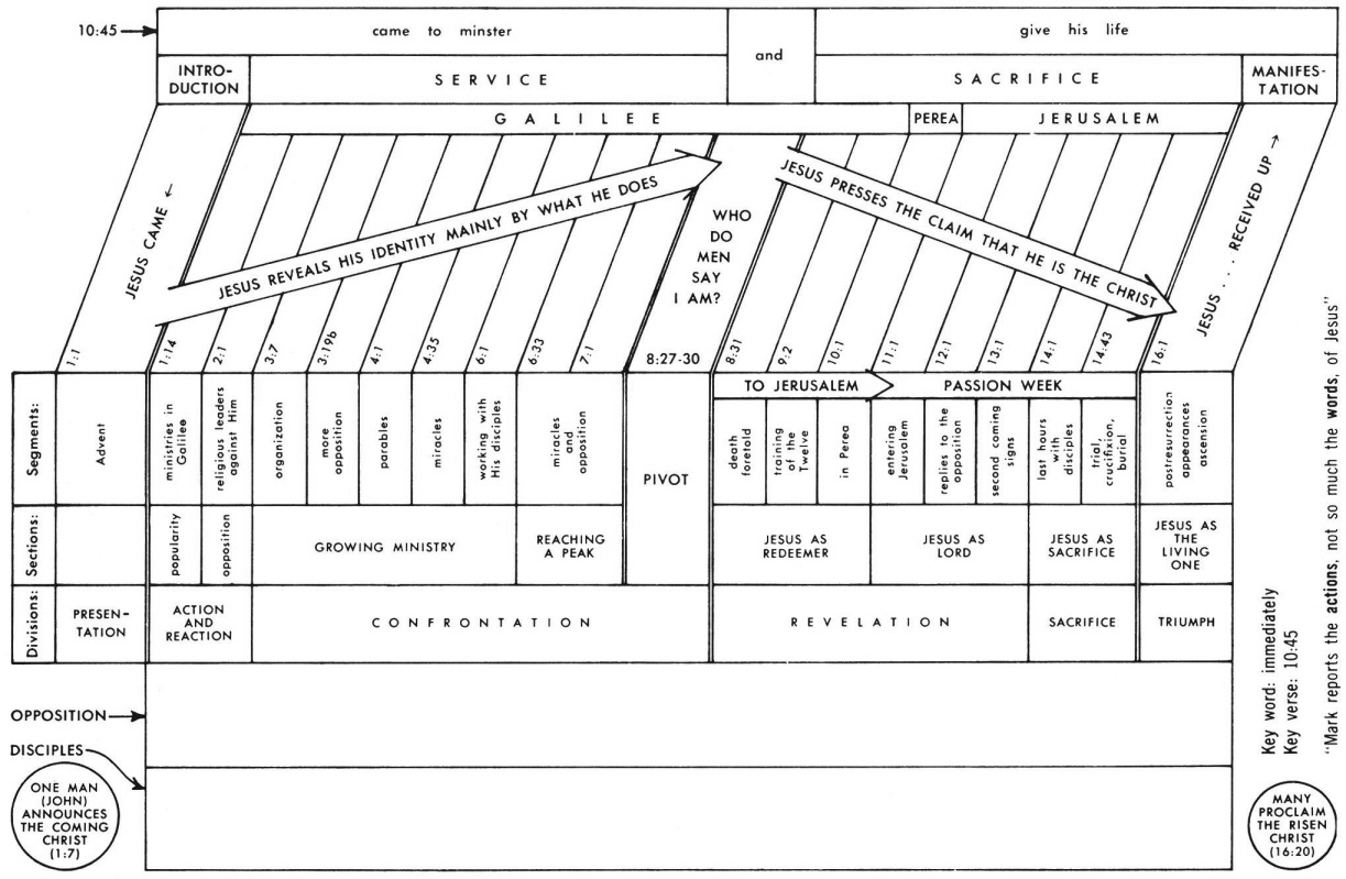
Mark 4 Commentary Precept Austin

Signal Chain Basics 93 How To Maximize Low Side Sensing Performance Planet Analog

Traffic Light Design Using Flip Flop 26 Pages Analysis In Doc 1 9mb Updated 2021 Ryleigh Study For Exams

Variable Power Supply With Ua78g Ua79g

Signal Chain Basics 93 How To Maximize Low Side Sensing Performance Planet Analog

Signal Chain Basics 93 How To Maximize Low Side Sensing Performance Planet Analog

Two Way Traffic Light Circuit Using 555 And Cd4017 Traffic Light Circuit Electronics Basics

Signal Chain Basics 93 How To Maximize Low Side Sensing Performance Planet Analog

Trafficlightcontrol Block Diagram Engineeringstudents Block Diagram Pic Microcontroller Diagram

Traffic Light Design Using Flip Flop 26 Pages Analysis In Doc 1 9mb Updated 2021 Ryleigh Study For Exams

Traffic Light Design Using Flip Flop 26 Pages Analysis In Doc 1 9mb Updated 2021 Ryleigh Study For Exams

This Two Way Traffic Light Circuit Using 555 And Cd4017 Achieves The Functionality Of A Typical Two Way Traffic Light Traffic Light Circuit Traffic

Traffic Light Design Using Flip Flop 26 Pages Analysis In Doc 1 9mb Updated 2021 Ryleigh Study For Exams
Traffic Light Design Using Flip Flop 28 Pages Summary In Google Sheet 1 9mb Latest Update Alina Study For Exams

How Does Gps Work Eetimes